 PATENT SPECIFICATION UK 320034
Application Date: June 1, 1928. No. 16,018 /28. 320,034
Complete Left: Nov. 28, 1928. Complete Accepted: Oct. 1, 1929.
PROVISIONAL SPECIFICATION.
Improvements in Rotary Machines for Manufacturing Glass Hollow-ware and other Moulded Articles of Glass.
We, John Moncrieff Limited, a British Corporation, having its registered offices at St. Catherine’s Road, Perth, Scotland, and Alexander Francis McNish, of 25, Balhousie Street, Perth, aforesaid, citizen of the United States of America, do hereby declare the nature of this invention to be as follows:—
This invention relates to rotary machines for the manufacture of glass bottles or other hollow-ware or moulded articles of glass, wherein the machine comprises blow heads, parison moulds and finishing moulds revolving in a horizontal plane.
The invention consists broadly of a table and mould-supporting column rotatable together through part of a circle to bring a blowhead and parison mould into position for gathering a charge of glass, the column which carries the moulds being then stopped while the table returns to its normal position, mechanism actuated by the reverse movement of the table causing the parison mould to dip into the charging trough and to be withdrawn therefrom with the gather, whilst transferring a parison from one of the parison moulds to a finishing mould. The reverse movement of the table may also be caused to operate shears for trimming the parison and for opening the finishing moulds to enable the moulded article to be removed.
The invention furthermore consists in mounting the finishing moulds to rise and fall, preferably by hinging the finishing moulds upon the central rotatable column, and in providing the table with an inclined track which cooperates with the finishing moulds to raise the same into transfer position to receive the parison, and to allow the finishing moulds to fall in readiness for delivering the moulded article.
The table oscillates through an angle equal to the angle between the moulds, as for example 120 degrees in the case of a three-mould machine, and mechanism is provided whereby the table drives the mould-supporting column during the forward movement of the table, whilst movement of the mould-supporting column is arrested during the reverse movement of the table.
Suitable cams are mounted upon the oscillating table for raising and lowering the parison moulds, for opening and closing the same, for operating the trimming shears, and for opening and closing the neck ring of the blow head or parison mould.
The machine preferably comprises a fixed vertical spindle mounted upon a suitable base and rotatably supporting a triangular or flatsided column to which the finishing moulds are hinged. The column terminates at its lower end in a flange just above an oscillatory table which is oscillated through 120° by means of any suitable gearing, such as a toothed quadrant turning with the table and meshing with a rack reciprocated by connection to a crank pin rotated from any convenient source of power. A driving pin or equivalent device is actuated at the end of the reverse movement of the table to lock the flange of the mould-supporting column to the table during the forward movement of the latter, and a locking-pin or like device adapted to be projected through an arcuate slot in the table is provided to lock the flange of the mould-supporting column against movement during the reverse motion of the table. The driving pin and locking pin may be actuated by means of cam and roller mechanism or other suitable mechanism situated beneath the table.
Upon the oscillatory table are fixed a series of cams for operating the parison mould, neck mould and trimming shears. The parison moulds may be each carried by brackets or crossheads upon vertical guide spindles attached to the central column and the parison mould may be raised by means of a lifting rod having a roller engaging a crown cam on the table. The parison mould may be opened and closed by link mechanism controlled by a roller working in a cam groove on the table and the neck ring of the parison mould and the shears may be similarly opened and closed by the cooperation of rollers with cam grooves on the table.
Also mounted upon the oscillatory table is a track or rail which extends substantially two thirds of the way around the table, rising upwards and outwards from its lower extremities which are fixed to the table. The track thus forms a rail inclined downwards and inwards on both sides of an elevated substantially horizontal portion, which is situated at such a height and at such a distance from the central column as to support the finishing moulds in the transfer position.
The finishing moulds are each mounted upon a base plate hinged to the central column, so that the base plate normally hangs downwards at an angle, with the finishing mould projecting outwards and upwards therefrom, so that the neck of the bottle can be conveniently grasped when the finishing mould is in the delivery position.
During the reverse movement of the table, the rear end of the track mounted on the table engages rollers on the base plate of one of the finishing moulds and raises the mould until it rides upon the horizontal portion of the track, in which position it is brought beneath the parison which at that moment is lowered into the finishing mould. The opening and closing of the finishing mould is effected by cams on the track engaging linkwork or other mechanism mounted on the base plate of the finishing mould. Whilst one of the finishing moulds is being raised into transfer position by the returning track, the preceding finishing mould falls down the front inclined portion of the returning track into its normal inclined position ready for delivering the moulded article, which is delivered, when the finishing mould has travelled round the machine and again meets the rear end of the oscillating track, by a cam on the track operating to open the finishing mould. The machine is preferably of the suction-gathering type, the charge of glass being drawn into the parison mould in the dipping position by a vacuum created in the blow head of the parison mould, the blow head being connected to suction and pressure pipes controlled by automatically-actuated valves. As soon as the charge of glass has been drawn in, the vacuum valve closes and the parison mould travels from the gathering position to the transfer position, where the parison mould opens and the parison is transferred to the finishing mould. The bottle is then blown during the travel of the finishing mould from the transfer position to the position at which it is lowered in readiness for delivering the moulded article. In order to allow the finishing mould to fall down the inclined track as it leaves the transfer position, the neck ring of the blow head is opened by mechanism operated as already described from one of the cam grooves on the table. The blow head is provided with the usual plunger which is momentarily depressed to form the depression in the neck of the parison during the gathering operation.
Dated this 31st day of May, 1928.
JOHNSONS,
Chartered Patent Agents,
41, St. Vincent Place, Glasgow, and
10, Stafford Street, Edinburgh.
COMPLETE SPECIFICATION.
Improvements in Rotary Machinesfor Manufacturing Glass Hollow-ware and other Moulded Articles of Glass.
We, John Moncrieff Limited, a British Corporation, having its registered offices at St. Catherine’s Road, Perth, Scotland, and Alexander, Francis McNish, of 25, Balhousie Street, Perth, aforesaid, citizen of the United States of America, do hereby declare the nature of this invention and in what manner the same is to be performed, to be particularly described and ascertained in and by the following statement:—
This invention relates to rotary machines for the manufacture of glass bottles or other hollow-ware or moulded articles of glass, wherein the machine is of the suction gathering type and comprises suction . and blow heads, parison moulds and finishing moulds revolving in a horizontal or substantially horizontal plane.
The invention consists broadly of a table or support and mould-supporting column rotatable together through part of a circle to bring a blowhead and a rising and falling parison mould into position for gathering a charge of glass, the column which carries the moulds being then stopped while the table returns to its normal position, mechanism actuated by the reverse movement of the table causing the parison mould to dip into the charging trough and to be withdrawn therefrom with the gather, whilst transferring a parison from one of the parison moulds to a finishing mould. The reverse movement of the table may also be caused to operate shears for trimming the pari-son and for opening the finishing moulds to enable the moulded article to be removed.
Machines for forming glassware other than of the suction gathering type are known in which a gob of glass is dropped into each parison mould in succession, the several sets of moulds each consisting of an inverted parison mould, a neck mould and a finishing mould to which the parison is transferred by turning it over, the several moulds being mounted on a carrier rotatable step-by-step around a central column driven by a cam frame which carries cam plates for operating the neck and finishing moulds and which is connected to said carrier to rotate therewith as the latter advances and disconnected from the carrier and returned while the latter remains stationary. In such machines the parison mould does not rise and fall to receive the charge of glass, and is not opened and closed by the returning cam frame.
The invention furthermore consists in mounting the finishing moulds to rise and fall, during the return movement of the table, preferably by hinging the finishing moulds upon the central rotatable column, and in providing the table with an inclined track which cooperates with the finishing moulds to raise the same into transfer position to receive the parison, and to allow the finishing moulds to fall in readiness for delivering the moulded article.
The table oscillates through an angle equal to the angle between the moulds, as for example 120 degrees in the case of a three-mould machine, and mechanism is provided whereby the table drives the mould-supporting column during the forward movement of the table, whilst movement of the mould-supporting column is arrested during the reverse movement of the table.
Suitable cams are mounted upon the oscillating table for raising and lowering the parison moulds, for opening and closing the same, for operating the trimming shears, and for opening and closing the neck ring of the blow head or parison mould.
The accompanying drawings illustrate one example of a glass bottle making machine constructed according to my invention, but it will be understood from the appended description that the illustrations are in some respects diagrammatic, parts of the machine having been omitted where it has been thought desirable in order to more clearly demonstrate the salient features of the machine.
Referring to the drawings (Figs. 1 and 2), the machine comprises a base 1 mounted upon screw-threaded legs adjusted vertically by nuts operated by chain and sprocket gearing la. The base 1 supports a fixed central vertical spindle 2. The spindle 2 extends almost the full height of the machine and upon it revolves a hollow triangular prism or flat-sided column 3 to which the finishing moulds 4 are hinged upon horizontal fulcrums 5. The lower end of the column 3 has a flange 6 which is supported by means of a ball bearing 7 just above a table 8 adapted to revolve upon a ball bearing 9. The table 8 revolves with a toothed quadrant 10 which meshes with a rack 11 (see also Fig. 3) having a fulcrum at one end upon a crank pin 12 carried by a wheel 13. The free end of the rack 11 is held in mesh with the quadrant 10 by vertical pins or rollers 14 on lugs 15 projecting from a loose ring 15a. The rack is guided between the pins 14. The wheel 13 is mounted to turn with worm gearing 16 driven from any suitable source of power and it will be understood that rotation of the wheel 13 will reciprocate the rack 11 which in turn will oscillate the quadrant 10 and table 8 through an angle of 120 degrees or one-third of a complete revolution. Any other suitable gearing may be provided for operating the table.
On the table 8 are mounted the cam plate 17 (Fig. 11) for opening and closing the parison moulds 18 and neck ring 51, the track 19 for raising and lowering the finishing moulds 4, the cams 20 and 20a for raising and lowering the parison moulds 18 for gathering and blowing, and also the cam 64 (Kg. 4) for operating the shears.
A driving pin 21 (Figs. 18 and 19) slides vertically in a housing 22 on the. underside of the table 8 and carries at its lower end a roller 23 which is adapted to ride over and under a fixed arcuate track 24 when the table oscillates. During the forward movement of the table 8, the roller 23 rides on the track 24 and the upper end of the driving pin 21 is projected by springs 34 into a hole 25 in the column flange 6, thereby locking the mould-supporting column to the table during the forward movement of the latter. At the end of its forward stroke, the driving pin 21 is withdrawn from the hole 25 in the flange 6 by a lever 26 which depresses a crosshead 27 on the driving pin 21. The lever 26 is connected by links 28 to a vertically movable locking pin 29 which moves in a fixed bracket or housing 35 in such manner that, when the lock-pin 29 is raised, the drive-pin 21 is lowered. The lock-pin 29 is raised and lowered by the provision on the lock-pin 29 of a roller 30 operating a cam groove 31 in the wheel 13. The locking-pin 29 when raised passes through an arcuate slot 32 in the table 8 into one of three locking holes 33 provided in the flange 6 of the mould-supporting column at 120 degrees apart. The end of the fixed track 24 is inclined so as to assist in drawing down the drive-pin 21 at the end of its forward stroke. The roller 23 rides under the track 24 on the return stroke of the table 8 and thereby holds the drive pin 21 out of operation. Thus the drive pin 21 rotates the mould-supporting column during each forward stroke and the locking pin 29 holds the mould-supporting column stationary during each return stroke of the table.
The parison moulds 18 (Figs. 1, 5 and 6) are each split as usual, the two halves being each carried by an arm 36 pivoted upon a bracket 37 which is fixed upon a spindle 38 and is fixed to a crosshead 38a fixed to vertical guide rods 39 which slide in brackets 40 fixed to the mould-supporting column 3. The lower ends of the guide rods 39 carry a crosshead 41 on which is mounted a roller 42 which cooperates with the cams 20 and 20a on the oscillating table 8 to raise and lower the parison moulds. The parison mould is opened and closed by connecting the parison arms 36 by pin and slot connections to bell-cranks 43 turning on the rods 39 and connected by rods 44 to a crosshead 45 (similar to the crosshead 53a of Figs. 16 and 17) having a roller 45a (Fig. 16) movable in a slotted link 46 carried by a slide 46a moved towards and away from the parison by an arm 47 projecting from a vertical shaft 48 which carries at its. lower end a roller 49 running in a cam groove 50 (Fig. 4) in the cam plate 17. The cam groove 50 is shaped to close and open the parison moulds at the required times and the cams 20 and 20a raise and lower the parison as required. The slotted link 46 allows the parison mould to be opened and closed either in its raised or lowered position.
The holder of the neck ring 51 (Figs. 16 and 17) of the parison mould similarly consists of a pair of pivoted arms 52 opened and closed by actuating links 53 connected by a crosshead 53a having a central roller which works in a slotted link 54 having a slide 54a moved towards and away from the mould by a lever 55 projecting from a vertical shaft 56 which carries on an arm at its lower end a roller 57 which runs in a cam groove 58 (Figs. 2 and 4) in the cam plate 17.
A shear arm 59 (Fig. 4) for each parison mould is pivoted on a vertical shaft 60 carried in bearings fixed on the cross head 38a (see Fig. 5) and is operated by a lever 61 on a shaft 61a, the lever 61 having a long pin 616 engaging an arm 62 at the lower end of the shaft 60, a lever on the lower end of shaft 61a having a pin or roller 63 which cooperates with a cam 64 on the cam plate 17. An annular guide 65 fixed on the oscillating table 8 guides the movement of the rollers 63 as the table oscillates to and fro in relation to the column.
The track 19 for raising and lowering the finishing moulds 4 extends substantially 2/3 of the way around the table and consists (as shown in Figs. 1 and 3) of a rail or bar bent to the form shown so that it rises upwards and outwards from each end to a level portion 19a which is at such a distance from the central column and at such a height as to support the finishing mould 4 in an upright position as shown. The finishing moulds 4 are each mounted upon a base plate or member 66 which is pivoted on the fulcrum 5 and has end rollers 67 which run upon the track 19.
The base plate normally hangs downwards at an angle, with the finishing mould projecting outwards and upwards therefrom, so that the neck of the bottle can be conveniently grasped when the finishing mould is in the delivery position.
The opening and closing of the finishing mould 4 is effected by pivoting the two halves of the finishing mould on a pin 68 (Figs. 13 and 14) on the base member 66 and providing two pins, rollers or projections 69 on a slide 71 for engaging an arcuate slot 70 in each half of the mould to close and open the mould when the slide 71 is reciprocated. The slide; 71 is operated by providing it with a roller 72 which rides along a earn bar 73; (Fig. 15) fixed at the highest point of the track 19 for closing the mould. The cam bar 73 is pivoted at 74 and held in the path of the roller 72 by a spring 75. A fixed cam 99 (Figs. 1 and 3) opens the finishing mould at the delivery position.
The charge of glass is drawn into the parison mould by creating a vacuum in the blow head 76 of the parison mould. This is carried in a bracket 77 (Figs. 7 and 8) and has a plunger 78 connected to links 79 and 80, the latter having a roller 81 movable in a slotted link 82 carried by slide rods 83, which slide in cross heads 84 and 85. Through the crosshead 84 slides the spindles 38. The crosshead 85 is fixed to the column 3. A roller 86 carried by the slide rods 83 engages a cam groove in a fixed cam 87 at the head of the machine. A pipe 88 leads to the blow head which has ports controlled by the plunger 78. The pipe 88 has connections 89 and 90 to a valve chest 91 containing a piston valve 92 which controls an air inlet pipe 93 and a vacuum pipe 94. The valve 92 is lifted by a roller 95 (Fig. 12) on its lower end cooperating with a cam track 96 fixed on the column 3 and is depressed by a finger 386 on shaft 38. Figs. 9 and 10 show a timing valve 100 for regulating the supply of compressed air to the blow head and for controlling the vacuum connection. This timing valve 100 is mounted on the top of the triangular column 3 (Fig. 12) within a cylindrical valve casing 101.The valve 100 thus remains stationary whilst the valve case 101 rotates with the triangular column. The valve 100 is interposed between the blow-heads 76 and the valve 92 (Fig. 12) and the pipes 88 from the three blow-heads open into the valve case 101. The valve 100 has on its underside three slots or recesses 102, 103 and 104 which connect respectively to a vacuum pipe 89 and to compressed air pipes 90 and 90a. When the port 88a (Fig. 12) traverses the slot 102, the blow-head is connected to the vacuum pipe for gathering the charge. When the port 88a traverses slot 104, the parison is blown, and when the port 88a traverses slot 103, the blow-head is supplied with air for blowing the bottle.
In order that the operation of the machine may be more readily understood, the sequence of operations carried out by one of the parison moulds will now be described.
As shown in Figs. 1 and 3, the position at which the parison mould dips for gathering the charge of glass is designated position No. 1, the position at which the parison is transferred to the finishing mould is designated No. 2 position and the position No. 3 is the position in which the parts have completed their sequence of operations.
The parison mould 18 as it approaches the gathering position is closed and the plunger 78 is depressed (as shown in Fig. 7) by the cooperation of cam 87 with roller 86 in readiness to form the usual depression in the neck of the parison. The parison mould is brought into the gathering position by the forward rotation of the table 8. As soon as the latter completes its forward movement, the column 3 is locked in a stationary position and the parison mould is then in position No. 1 with the roller 42 resting on the top of the cam 20a. As soon as the table 8 reverses, the cam 20a is moved from under the roller 42, causing the parison mould to dip into the glass in the furnace forehearth 97. At this moment the blow-head connections are in the position shown in Fig. 7, i.e. the blow-head is connected to the vacuum or suction pipe 94 and a charge of glass is thus drawn into the parison mould.
Just before the table 8 reaches the end of its reverse movement, cam 20 raises the parison mould. At the same time, the shear blade 59a is operated by its cam to trim the parison.
The table 8 then commences its forward movement and carries with it the column 3 and parison moulds. During this movement the finishing mould 4 hangs down in the position shown in Figs. 1 and 2. During this movement also, cam 96 lifts valve 92, closing vacuum connection 89, 94 and opens air connection 90, 93. The timing valve 100, however, cuts off communication between air pipe 90 and blow head until groove 104 connects with port 88a. In the meantime, plunger 78 has been withdrawn by cam 87 operating roller 86. The charge of glass is thus blown. The shears are lowered until just clear of 6 the parison by mechanism not shown. As soon as the parison mould reaches No. 2 position, the table 8 is at the end of its forward stroke. On the reverse movement of the table, the returning track 19 lifts the finishing mould 4 to its highest position. At the same time the parison is released from the parison mould by the cooperation of the earn groove 50 with the roller 49, and the parison is dropped into the finishing mould by the cam 20 riding from under the roller 42. The finishing mould is then closed upon the parison by the cam bar 73 on the high part of the track 19. The table 8 then commences its forward travel again and the bottle is blown as the parison travels from the position No. 2 to position No. 3. On the next reverse movement of the table 8, the neck ring 51 is opened by the cooperation of the cam groove 58 with the roller 57. This allows the cam 20a to raise the blow head, neck ring and open parison mould to their highest positions. At the same time the finishing mould rides down, the returning track 19 until it again hangs downwards. The neck ring and parison mould close during the returning movement of the track so that, on the next forward movement of the table, the parison mould is in readiness for gathering and the plunger is depressed, the parison mould moving into the gathering position. The finishing mould with the blown bottle is carried round by the intermittent rotation of the table 8 until, when it again reaches the position No. 2 and still hangs downwards, it is struck by a fixed cam 99 on the rear end of the track 19 to open the finishing mould in readiness for enabling the finished article to be removed as the opened finishing mould is being lifted by the reverse movement of the track.
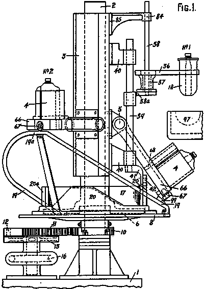
Fig. 1 is a side view of the general assembly of the machine.
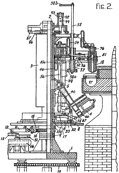
Fig. 2 is a half-sectional elevation of the machine, and a half outside view of the machine with parts removed.
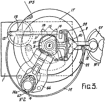
Fig. 3 is a general plan view of parts of the machine.
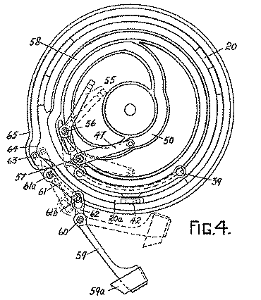
Fig. 4 is a plan view of the cam grooves in the table showing parts of the operating mechanism.
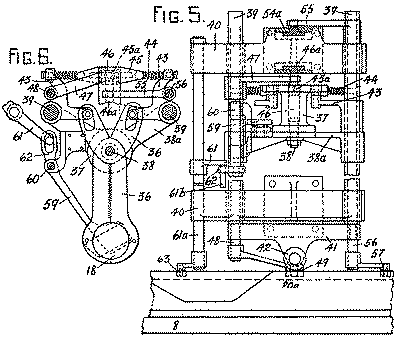
Fig. 5 is an elevation, partly in section, looking towards one of the parison moulds.
Fig. 6 is a detail plan view of the parison mould.
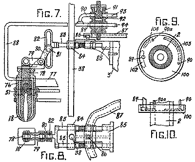
Fig. 7 is a part sectional elevation of the parison mould and valves.
Fig. 8 is a plan view of the parts shown in Fig. 7.
Figs. 9 and 10 are detail views of the air and vacuum distributing valve.

Fig. 11 is a side view of the table cams.
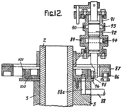
Fig. 12 is a sectional view showing the air and vacuum control valve, the valve being turned through 90° for convenience of illustration.
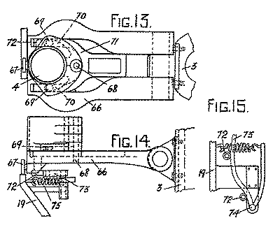
Figs. 13 and 14 are plan and side views of the finishing mould.
Fig. 15 is a plan view of the track cam for opening and closing the finishing mould.
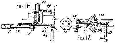
Figs. 16 and 17 are side and plan views of the neck ring mechanism.
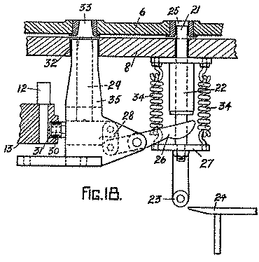
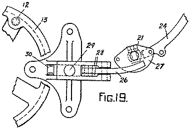
Figs. 18 and 19 are a fragmentary sectional elevation and plan respectively of the locking and driving pins and associated part.
Having now particularly described and ascertained the nature of our said invention and in what manner the same is to be performed, we declare that what we claim is :—
- A rotary machine of the suction gathering type for making glass hollow-ware or other moulded, articles of glass comprising suction and blow heads, rising and falling parison moulds, and finishing moulds, all of which revolve in a horizontal or substantially horizontal plane, a table or support and mould-supporting column, means for rotating said table and column together through part of a circle to bring a parison mould into gathering position, means for returning the table to normal position while the column remains stationary, mechanism for raising &lowering the parison mould & blow head & for gathering a charge of glass, and mechanism for transferring a parison from a parison mould to a finishing mould.
- A rotary machine of the suction gathering type for making glass hollow-ware or other moulded articles of glass comprising suction and blow heads, rising and falling parison moulds, and finishing moulds, all of which revolve in a horizontal or substantially horizontal plane, a mould-supporting column, mechanism for intermittently rotating said column through part of a circle, mechanism for raising and lowering the parison mould and blow head and for gathering a charge of glass while the column remains stationary, and mechanism for transferring the parison to a finishing mould during the succeeding period of rest of the column.
- A machine as claimed in claim 1 in which the rising and falling movement of the parison moulds, the gathering mechanism and the transfer mechanism are actuated by the reverse movement of the table.
- A rotary machine of the suction gathering type for making glass hollow-ware or other moulded articles of glass comprising suction and blow-heads, rising and falling parison moulds, and finishing moulds, all of which revolve in a horizontal or substantially horizontal plane, a mould-supporting column, means for intermittently rotating the column through an angle equal to the angle between the moulds, and mechanism for successively raising and lowering the parison mould and blow head for gathering the charges of glass and for transferring the parisons to the finishing moulds during the periods of rest of the column.
- A rotary machine as claimed in claim 4 having a table or support, mechanism for oscillating the table about its centre, and mechanism actuated by the reverse movements of the table for raising and lowering the parison moulds, and for operating the gathering and transferring mechanisms.
- A machine as claimed in claim 1, 3 or 5 having parison trimming mechanism and/or finishing mould opening and closing mechanism operated by the reverse movement of the table.
- A rotary machine as claimed in any of the preceding claims having the finishing moulds mounted upon the column to rise and fall during the return movement of the table, and mechanism for raising the finishing moulds into position to receive a parison.
- A machine as claimed in claim 7 in which the finishing moulds are hinged upon the column.
- A machine as claimed in claim 5, 7 or 8 having an oscillating inclined track for raising and lowering the finishing moulds.
- A rotary machine according to claim 1, 3, 5, 6 or 7 having mechanism for driving the column from the table during the forward movement of the latter and for arresting the column during the reverse movement of the table.
- A rotary machine according to claim 9 having mechanism for driving the column during the forward movement of the track and for arresting the column during the reverse movement of the track.
- A rotary machine according to claim 10 wherein the parison moulds and/or neck ring are operated by cams on the table.
- A rotary machine according to claim 11 wherein the parison moulds and/or neck ring are operated by cams oscillating with the track.
- A rotary machine according to claim 9 having mechanism on the track for cooperation with the finishing moulds to open and close the latter.
- A rotary machine as claimed in claim 1 having the column rotatably mounted upon a fixed vertical spindle having a base which supports the machine.
- A rotary machine as claimed in claim 1 having a toothed quadrant turning with the table, a rack meshing with the quadrant, and mechanism for reciprocating the rack.
- A rotary machine as claimed in claim 10 having a driving pin or like device actuated at the end of the reverse movement of the table to lock the column to the table and released at the end of 40 the forward movement of the table, and a locking pin or like device adapted to be projected through an arcuate slot in the table so as to engage and lock the column during reverse movement of the table. A rotary machine according to claim 17 in which the driving pin and locking pin are interconnected for alternate operative action, substantially as described.
- A rotary machine as claimed in claim 9 having the track constructed in the form of a rail and shaped substantially as herein described and illustrated for the purpose specified.
- A rotary machine according to any of the preceding claims, wherein the suction and blow heads are connected to automatically controlled suction and pressure pipes, substantially as described.
- A rotary machine of the suction gathering type for the manufacture of glass hollow-ware and other moulded articles of glass constructed and arranged to operate substantially as herein described with reference to the accompanying drawings.
Dated this 22nd day of November, 1928.
JOHNSONS,
Chartered Patent Agents,
41, St. Vincent Place, Glasgow, and
10, Stafford Street, Edinburgh.